Introduction:
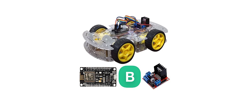
We're going to go on an exciting adventure to build our very own WiFi-controlled car in today's tutorial. This project offers a hands-on introduction to the Internet of Things (IoT) by combining the capabilities of the ESP8266 NodeMCU board with the power of the Blynk application.
Materials Needed:
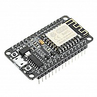
- ESP8266 NodeMCU board
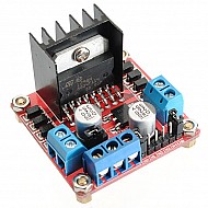
- L298N Motor Driver
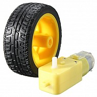
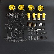
- DC motors with wheels + Chassis
- Power source (e.g., battery pack)
- Jumper wires
- Smartphone with the Blynk app installed
Step 1: Motor Driver Connections:
- Connect the positive terminal of the power source to the
+12Vinput on the L298N motor driver. - Connect the negative terminal of the power source to the
GND(ground) on the L298N motor driver.
Step 2: Motor Connections:
- Connect the positive terminal of the first DC motor to the
OUT1terminal on the L298N motor driver. - Connect the negative terminal of the first DC motor to the
OUT2terminal on the L298N motor driver. - Connect the positive terminal of the second DC motor to the
OUT3terminal on the L298N motor driver. - Connect the negative terminal of the second DC motor to the
OUT4terminal on the L298N motor driver.
Step 3: Motor Driver Control Pins:
- Connect the
ENA(Enable A) on the L298N motor driver to a PWM-enabled pin on the ESP8266 NodeMCU (e.g.,D1). - Connect the
IN1on the L298N motor driver to a digital pin on the ESP8266 NodeMCU (e.g.,D5). - Connect the
IN2on the L298N motor driver to another digital pin on the ESP8266 NodeMCU (e.g.,D6). - Connect the
ENB(Enable B) on the L298N motor driver to a PWM-enabled pin on the ESP8266 NodeMCU (e.g.,D2). - Connect the
IN3on the L298N motor driver to a digital pin on the ESP8266 NodeMCU (e.g.,D7). - Connect the
IN4on the L298N motor driver to another digital pin on the ESP8266 NodeMCU (e.g.,D8).
Step 4: Powering the ESP8266 NodeMCU:
- Connect the
Vinpin on the ESP8266 NodeMCU to the positive terminal of the power source. - Connect the
GNDpin on the ESP8266 NodeMCU to the negative terminal of the power source.
Step 5: Connection to Blynk App:
- Open the Blynk app on your smartphone.
- Create a new project and obtain the authentication token.
Step 6: Upload Code:
Upload the Arduino code provided in the previous response to your ESP8266 NodeMCU using the Arduino IDE.
Replace "YourAuthToken", "YourWiFiSSID", and "YourWiFiPassword" with your Blynk authentication token and WiFi credentials.
Step 7: Blynk App Configuration:
- In the Blynk app, add a Joystick widget to Virtual Pin
V1. - Configure the Joystick widget to send values for X and Y axes.
Step 8: Test and Enjoy:
Power up your WiFi-controlled car and launch the Blynk app. Use the joystick in the app to control the movement of your car. Enjoy your DIY WiFi-controlled car!
Conclusion:
Well done! Using the ESP8266 NodeMCU board and the Blynk application, you have successfully constructed a WiFi-controlled car. You will learn the fundamentals of IoT through this project, which also provides access to additional customization and exploration options. Play around with extra features and sensors to improve your WiFi-enabled vehicle.
Remember to modify the code as necessary based on the specific pins you choose during the hardware setup. Double-check all connections before powering up your project.
Happy tinkering, and don't forget to share your creations!


Leave a Comment