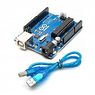
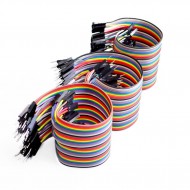
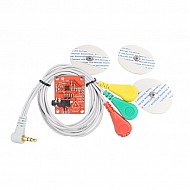
-1060x400h.jpg)
Hello,
In this tutorial, we are going to learn how to make an ECG machine using Arduino
Hardware Required
Software Required
What is ECG?
-
An electrocardiogram is a graphical representation of the heart's electrical waves. ECG helps in obtaining the person's heart rate and rhythm. The graph contains repetitive cycles of a person's heart rhythm. Each cycle contains P, Q, R, S intervals. The sinoatrial node of the heart produces the P wave. The Q, R, S waves are produced by the atrioventricular node. The P wave in an ECG indicates atrial depolarization. The Q, R, S waves indicate the ventricular depolarization. The T wave is ventricular repolarization. The QRS wave comprises of a small Q wave, a high R wave and a small S wave.
-
The R and S wave cause the transmission to the whole tissue.
Uses of ECG
ECGs can be used to investigate several heart conditions like chest pain, palpitations, dizziness and shortness of breath.
-
Arrhythmias: ECG can help detect irregular sinus rhythm.
-
Coronary heart disease: ECG can help detect obstacles in the blood flow due to build up of fatty substances.
-
Heart attacks: ECGs help detect if the blood supply to heart is suddenly stopped.
-
Cardiomyopathy: ECGs help detect if the walls of the arteries are thickened.
AD8232 Heart rate sensor
- AD8232 is a heart rate sensor which can detect ECG waves with the help of an integrated circuit. This sensor is used for mapping the electrical activity of the heart. It can be used for fitness bands where ECG or EKG can be measured. This module give an analog output as the ECG graph cannot be represented as a digital wave.
- ECG waves contain a lot of disturbance and are difficult to extract. The AD8232 module is designed to amplify and filter the disturbance to obtain the correct ECG wave.
- Operating Voltage - 3.3V
- Analog Output
- Leads-Off Detection
- Shutdown Pin
- LED Indicator
- 3.5mm Jack for Biomedical Pad Connection or Use three-pin header.
Interfacing AD8232 with Arduino
- As you can see in the above picture, to obtain the accurate ECG wave we need to connect the terminals at these points. Also, electrodes can provide electric shocks to the person attached. So make sure you use a low power AC supply like 5V as the power supply.
Pins on AD8232 |
Pins on Arduino Uno |
GND |
GND |
3.3V |
3.3V |
Output |
A0 |
LO- |
Digital Pin 11 |
LO+ |
Digital Pin 12 |
The working concept of the ECG
- The 3 connected leads send the data to the AD8232 module.
- The IC on the AD8232 module filters out the disturbance and amplifies the ECG wave.
- This analog data is then sent to the Arduino board.
- Arduino board then displays this data in the form of an ECG wave on the Serial Monitor.
Arduino Code
void setup() {

  Serial.begin(9600);
  pinMode(10, INPUT);
  pinMode(11, INPUT); -

}

void loop() {

  if((digitalRead(10) == 1)||(digitalRead(11) == 1)){
    Serial.println('!');
  }
  else{

      Serial.println(analogRead(A0));
  }

  delay(1);
}
- The code for this project is very simple. Upload the code.
- You will see something like this on the Serial monitor after connecting the leads.


Leave a Comment