-1060x400h.jpg "Arduino Keypad door lock system")
Hello,
In this tutorial, we are going to learn how to build a door lock system using Arduino.
Hardware Required
Software Required
-
The objective of this project is to make a door lock that opens with a password. This password has to be entered through a keypad.
-
If the entered password matches the initial password stored on the Arduino, then the door will unlock.
-
If the password does not match the initial password, then the LCD Display will say "Wrong password".
-
It also has an additional function to change the current password. You need to press the '#' key. After pressing this key, the LCD will ask you to enter the current password. After entering the current password, it will ask you to enter the new password. This is how the password will be changed.
4x4 Keypad
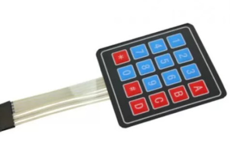
- 4x4 keypad contains 16 keys. 12 telephonic keys and 4 keys indicating the alphabets "A, B, C, D"
- As there are 4 columns and 4 rows, only 8 pins are needed to take input from the whole keypad.
Relays
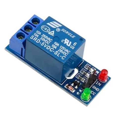
- A relay is an electromagnetic switch that can be used to control the flow of electric current in a circuit. The core component of a relay is an electromagnet which can be activated whenever needed.
- Relays can also work as amplifiers. All you need to switch on a relay is a tiny current. And in turn, relays can complete a much larger current circuit. So the small current can be leveraged into producing a much larger current. This is how relays are used as amplifiers.
- Relays were invented by the American pioneer of electromagnetism Joseph Henry in the year 1835. In a demonstration in New Jersey, he used a smaller electromagnet to switch a larger one on and off.
Circuit Diagram
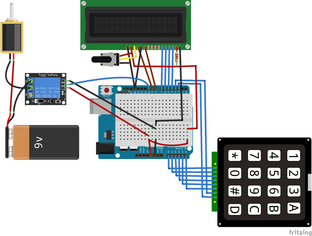
- Connect the first 6 pins of the keypad to the six analog pins of Arduino Uno. Connect the last two pins to digital pins 2 and 3 on the Arduino board.
- Connect pin 1 (VSS) on the LCD, to GND on the Arduino.
- Connect pin 2 (VDD), to the 5V pin on the Arduino.
- Connect pin 3 (V0), to the middle of the 10k potentiometer and connect the other two pins on the potentiometer to 5V and GND on the Arduino.
- Connect pin 4 (RS), to pin 7 on the Arduino.
- Connect pin 5 (R/W), to the GND pin on the Arduino.
- Connect pin 6 (ENABLE), to pin 6 on the Arduino.
- Connect pins 11, 12, 13, and 14 (data pins) to pins 5, 4, 3, and 2 on the Arduino.
- Connect pin 15, which is the LCD’s backlight pin, to 5V on the Arduino through the 220-ohm resistor.
- Connect pin 16 on the Arduino, which is the negative pin of the backlight, to GND on the Arduino.
Now we will connect the DC lock directly to the Arduino. But the lock requires more than 5 volts so we will need to connect a relay in between the lock and the Arduino.
- Connect the signal pin of the relay to Arduino pin 10. connect the VCC and GND to 5V and GND to Arduino.
- Connect the positive terminal of the battery to the positive terminal of the door lock and the negative terminal to the negative of the door lock via relay.
Working concept
- The working concept of this project involves four processes: Input, processing and matching, LCD output, and door lock/unlock.
- At first, after setting the password, the user inputs the password via the keypad. The keypad sends this data to the Arduino board to check if the password is right or wrong.
- If the password is right, the Arduino board will further send the command to both the LCD and the Door lock via relay.
- The command sent to the LCD will be to show the text "Pass accepted". The command sent to the door lock will be to open the lock.
- If the password typed is wrong, then the Arduino will only send a command to the LCD stating "Wrong password".
- This completes the concept cycle for this project.
Arduino code
- The initial set password is 1234.
Upload the code to the Arduino board. Perform the circuit diagram.
Now your Arduino keypad door lock is ready for use.


Leave a Comment