15 Dec
-1060x400h.webp "Interfacing the pulse rate sensor with Arduino")
Hello,
In today's world, pulse rate sensors are getting more and more known because of the use of smartwatches, smart bands and medical equipment has risen exponentially. Knowing the pulse of a patient can be pertinent is saving anyone's life. Smart watches can detect arrhythmias which can save someone's life if detected early.
In this article, we are going to learn more about the construction and working principle of the pulse sensor. We are also going to look at interfacing this sensor with Arduino.
Hardware Required
Software Required
Working principle of the Pulse rate sensor
- The pulse rate sensor works just like any other sensor. It senses the required data, it either processes the data itself or sends it back to the microcontroller board for processing. The difference between all such sensors is the data which they are collecting.
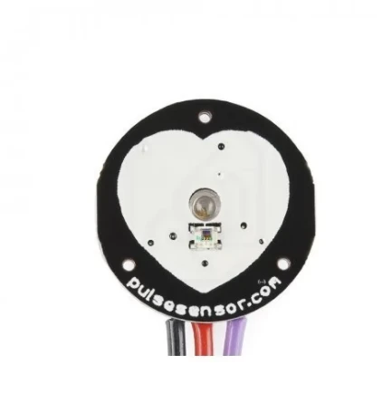
- As you can see from the above picture, this is the front side of the pulse rate sensor. It has a heart shape drawn on it. The pulse rate sensor basically consists of three different components: two led sensors and one ambient light sensor.
- To measure your pulse rate, you have to put a finger on to the front side of this sensor.
- The led will shine the light on to you veins and the ambient light sensor will measure the blood flowing through your veins. The blood flow is detected because as the blood flows, the intensity of the light from the led sensor varies. This variation is detected by the ambient light sensor and that is how blood flow is detected.
- Once the blood flow has been measured, the heart rate can be easily calculated.
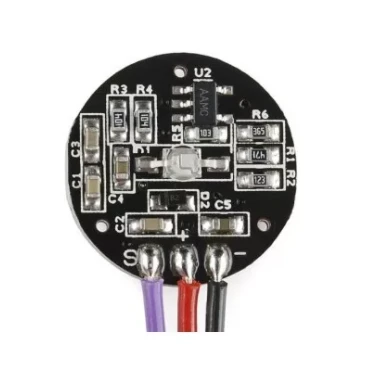
- The above picture shows the back side of the pulse rate sensor. This side of the sensor contains all the circuitry involved in making the sensor. The function of this circuit is to clear out the outside noise which might hinder with the blood flow data. This circuit also helps in the sensing and amplifying of the data so that the amplified data can be understood easily by the microcontroller.
- The data sent by this sensor is in the Analog format. So when interfacing with Arduino, we are going to have to use an analog pin.
Circuit diagram
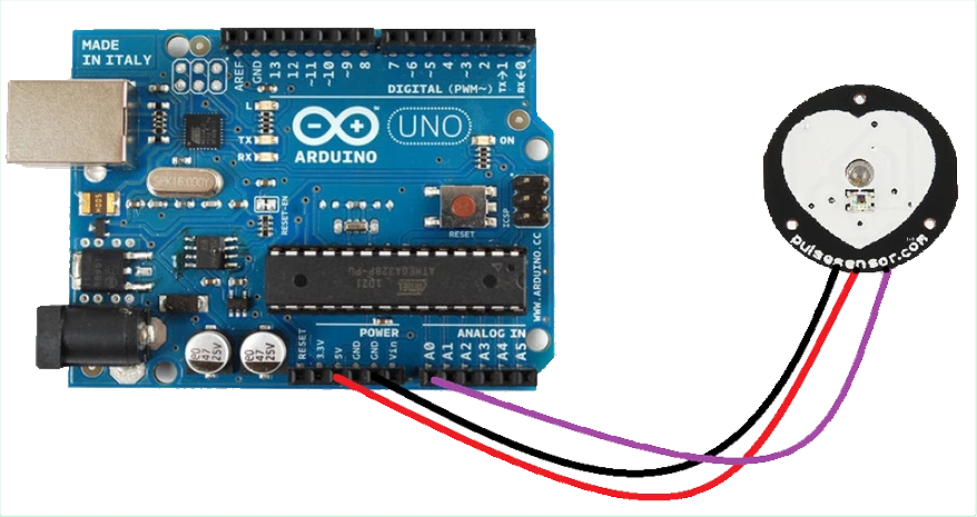
- Whilst interfacing with Arduino, the circuit diagram is pretty simple as there are only two components: The Arduino board and the pulse rate sensor.
- The pulse rate sensor has three pins: 5V, GND and D0 (Signal pin).
- The sensor provides data to the Arduino in analog form from this D0 pin.
|
Pins on Arduino Uno |
Pins on the Pulse rate sensor |
|
5V |
5V |
|
GND |
GND |
|
A0 |
D0 |
Arduino Code
int pulsePin = 0;
int blinkPin = 13;
int fadePin = 8;
int fadeRate = 0;


volatile int BPM;
volatile int Signal;
volatile int IBI = 600;
volatile boolean Pulse = false;
volatile boolean QS = false;


static boolean serialVisual = true;

volatile int rate[10];
volatile unsigned long sampleCounter = 0;
volatile unsigned long lastBeatTime = 0;
volatile int P = 512;
volatile int T = 512;
volatile int thresh = 525;
volatile int amp = 100;
volatile boolean firstBeat = true;
volatile boolean secondBeat = false;

void setup()
{
  pinMode(blinkPin,OUTPUT);
  pinMode(fadePin,OUTPUT);
  Serial.begin(115200);
  interruptSetup();

}


void loop()
{
   serialOutput();

  if (QS == true)
    {

      fadeRate = 255;
      serialOutputWhenBeatHappens();
      QS = false;
    }

  ledFadeToBeat();
  delay(200);
}

void ledFadeToBeat()
{
   fadeRate -= 15;
   fadeRate = constrain(fadeRate,0,255);
   analogWrite(fadePin,fadeRate);
}

void interruptSetup()
{

  TCCR2A = 0x02;
  TCCR2B = 0x06;
  OCR2A = 0X7C;
  TIMSK2 = 0x02;
  sei();
}

void serialOutput()
{
 if (serialVisual == true)
  {
     arduinoSerialMonitorVisual('-', Signal);
  }
 else
  {
      sendDataToSerial('S', Signal);
   }
}

void serialOutputWhenBeatHappens()
{
 if (serialVisual == true)
   {
     Serial.print("<<>> ");  //ASCII Art Madness
     Serial.print("BPM: ");
     Serial.println(BPM);

   }
 else
   {
     sendDataToSerial('B',BPM);
     sendDataToSerial('Q',IBI);
   }
}

void arduinoSerialMonitorVisual(char symbol, int data )
{
  const int sensorMin = 0;
  const int sensorMax = 1024;
  int sensorReading = data;
  int total_range= map(sensorReading, sensorMin, sensorMax, 0, 11);

  switch (total_range)
  {
    case 0:
      Serial.println("");
      break;
    case 1:
      Serial.println("---");
      break;
    case 2:
      Serial.println("------");
      break;
    case 3:
      Serial.println("---------");
      break;
    case 4:
      Serial.println("------------");
      break;
    case 5:
      Serial.println("--------------|-");
      break;
    case 6:
      Serial.println("--------------|---");
      break;
    case 7:
      Serial.println("--------------|-------");
      break;
    case 8:
      Serial.println("--------------|----------");
      break;
    case 9:
      Serial.println("--------------|----------------");
      break;
    case 10:
      Serial.println("--------------|-------------------");
      break;
    case 11:
      Serial.println("--------------|-----------------------");
      break;
  }
}


void sendDataToSerial(char symbol, int data )
{
   Serial.print(symbol);
   Serial.println(data);
}

ISR(TIMER2_COMPA_vect)
{
  cli();
  Signal = analogRead(pulsePin);
  sampleCounter += 2;
  int N = sampleCounter - lastBeatTime;

  if(Signal < thresh && N > (IBI/5)*3)
    {
      if (Signal < T)
      {
        T = Signal;
      }
    }

  if(Signal > thresh && Signal > P)
    {
      P = Signal;
    }


  if (N > 250)
  {
    if ( (Signal > thresh) && (Pulse == false) && (N > (IBI/5)*3) )
      {
        Pulse = true;
        digitalWrite(blinkPin,HIGH);
        IBI = sampleCounter - lastBeatTime;
        lastBeatTime = sampleCounter;

        if(secondBeat)
        {
          secondBeat = false;
          for(int i=0; i<=9; i++)
          {
            rate[i] = IBI;
          }
        }

        if(firstBeat)
        {
          firstBeat = false;
          secondBeat = true;
          sei();
- Pulse rate sensor can be very beneficial as they are used almost in each and every smart bands and watches. Pulse rate sensors have helped save so many lives and those are the main reasons that smart watches are gaining popularity these days.
- It has of course been vital in medical applications and SpO2 levels and heart rate both are measured by the same sensor. During the Covid-19 era, oxymeters and pulse meters have gained immense popularity as people want to measure their oxygen levels regularly to be safe from the Covid-19 pandemic.

Hot
-56 %
The Arduino Uno R3 Compatible board is an electronic hardware device used to build and program electronic circuits and projects. The board is based on..
₹574 ₹1,299

This is 10pcs of each (10 M-M, 10 M-F, 10 F-F) jumper cable Dupont wire for Arduino.
Specifications:
This is 10 pcs of each (total 30 pcs) ..
₹114

-45 %
Heart Rate data can be used in many Electronic design and microcontroller projects. But the heart rate data is difficult to read, however, the Pulse S..
₹127 ₹229

Leave a Comment